Generating Circuits
Instructions:
Remember, all assignments in CS 3410 are individual.
You must submit work that is 100% your own.
Remember to ask for help from the CS 3410 staff in office hours or on Ed!
If you discuss the assignment with anyone else, be careful not to share your actual work, and include an acknowledgment of the discussion in a collaboration.txt file along with your submission.
The assignment is due via Gradescope at 11:59pm on the due date indicated on the schedule.
Submission Requirements
You will submit your completed solution to this assignment on Gradescope. You must submit:
quine_mccluskey.c, which will contain your implementation in Task 1 and Task 2.tests.txt, containing your five new test inputs from Task 3.
Restrictions
- Do not modify any source files other than
quine_mccluskey.c.
Overview
You will implement a program that generates a logic circuit for a given truth table. This assignment covers the fundamentals of Boolean algebra and logic circuits.
Background
In class, we practiced a “recipe” for mechanically building a circuit to implement any Boolean function using its minterms. While this recipe works, it can yield pretty big and complicated circuits. There is an entire universe of techniques that attempt to design small, efficient circuits for a given truth table instead.
Consider the Boolean expression abc+ab¯c. (If you need a reminder about logic notation, see the lecture notes.) Notice that the c term doesn’t matter here: for all values of a and b, the value of the expression is the same regardless of whether c is true or false. So this expression is equivalent to ab. If you imagine the circuit to implement this expression, it’s a lot simpler: it just uses one AND gate, instead of the original’s four ANDs and an OR.
Compact Notation for Simple Boolean Expressions
We will need a simple way to represent the Boolean expressions we’ll be dealing with, which are generally “ands” of possibly-negated variables. The idea is to take conjunctions like a¯bc and to represent them with symbols, where the nth symbol corresponds to the nth input variable. The symbols are:
- 0: Negated variable, like ¯a in a real Boolean expression.
- 1: Non-negated variable, like a.
- x: Don’t care, i.e., like not including the variable in the “and” at all.
For example, if we have three variables named a, b, and c:
- The compact notation
110denotes the expression ab¯c. 01xdenotes ¯ab.1x1denotes ac.
Quine-McCluskey Algorithm
The Quine-McCluskey algorithm, a.k.a. the method of prime implicants, is a technique for finding smaller, more efficient Boolean expressions. Let’s define some terms:
- An implicant is a Boolean expression that “covers” several minterms:
for example,
1x1covers both111and101. In other words,1x1in our compact notation is equivalent to “111or101,” so it is an implicant that covers those minterms. - A prime implicant is an implicant that can’t be covered by some other, more general implicant.
The Quine-McCluskey algorithm works by finding these prime implicants and then using them to make the final Boolean expression.
The algorithm has two steps:
- Generate a set of all prime implicants by merging minterms.
- Select certain prime implicants to simplify the expression.
The first step works by starting with a set of minterms and
merging them together to produce implicants that cover them.
Two minterms can be merged if they differ in at most one position;
merging them produces an implicant where that one position becomes x (don’t care).
For example, the minterms 100 and 110 can be merged into 1x0
(check that you agree that the corresponding Boolean expressions are equivalent!).
But 100 and 111 cannot be merged into 1xx (because 1xx would also encompass the minterms 110 and 101, which are not in our original pair).
The first step works by checking every pair of minterms to see if they can be merged. Then, it repeats: it checks whether any pair of those implicants can be merged using the same rule. The step finishes when it can’t find any more more mergeable pairs. This step is Task 1 on this assignment.
The second step selects a smaller set of these prime implicants that covers the original set of minterms. We will describe the algorithm in Task 2.
Finally, we combine the reduced set of prime implicants with “or” to produce our final sum-of-products Boolean expression.
Program Overview
You will write a program that produces a simplified Boolean expression for a given truth table. Let’s use this truth table as an example:
| a | b | c | out |
|---|---|---|---|
| 0 | 0 | 0 | 0 |
| 0 | 0 | 1 | 1 |
| 0 | 1 | 0 | 0 |
| 0 | 1 | 1 | 1 |
| 1 | 0 | 0 | 0 |
| 1 | 0 | 1 | 0 |
| 1 | 1 | 0 | 0 |
| 1 | 1 | 1 | 1 |
Our program will work by taking the truth table’s minterms as input,
using our compact notation.
The minterms in this example are 001, 011, and 111.
The user would input a file with one minterm on each line:
001
011
111
If we wrote out the sum-of-products expression in standard notation, it would be ¯a¯bc+¯abc+abc.
When we run our program, however, it will produce the prime implicants 0x1 and 111.
These represent the simpler, equivalent Boolean expression ¯ac+abc.
The program will write the selected prime implicants in a file called output.txt.
Implementation
Task 0: Lab Section
In this lab, you will gain practice working with Boolean circuits (Section 1). You will also try a manual method for Boolean simplification (Section 2).
Section 1: Play Nandgame
This section of the lab uses Nandgame, a browser-based game about digital logic, to get experience with constructing circuits.
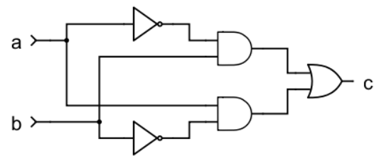
XOR. Open Nandgame and skip the first 4 levels (although feel free to come back later and try them yourself). We’ll start with the XOR circuit. Nandgame gives you a truth table for XOR, toolbox with some logic gates, and a canvas. Drag and drop components from the toolbox to the canvas, and connect inputs and outputs by clicking on the triangular inputs and clicking on the circular output of another component. Spend a few minutes trying to create your solution.
If you give up after trying for a while, here’s one possible solution:
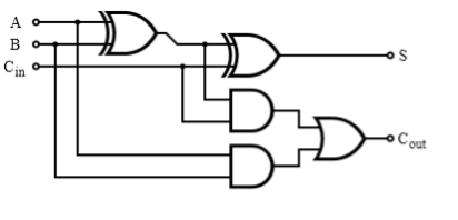
1-bit adder. Next, implement a 1-bit adder. Read more about half adders and full adders in the lecture notes. Try these levels in Nandgame.
Try it for at least a while before looking at one possible solution below:
Multi-bit adder. You can create an n-bit adder by cascading n full adders. Create the 2-bit adder in Nandgame by reusing the 1-bit adder provided. If you ever need help, feel free to ask a TA.
Ponder the fact that your strategy would be straightforward to extend to an n-bit adder for any n!
Checkoff #1: Show your two-bit adder to your TA.
Section 2: Karnaugh Maps
Karnaugh maps (a.k.a. K-maps) are a popular method for manually minimizing Boolean expressions. It has some similarities to the Quine-McCluskey algorithm you’ll implement, but it’s meant for human use instead of algorithmic implementation.
Introduction to Karnaugh Maps
A K-map is a 2-dimensional grid that represents a Boolean function. The rows and columns represent the inputs; the value in the cell (1 or 0) represents the output. This layout makes it possible to find groups of 1 cells, which can then be transformed into simplified expressions.
To construct a K-map, divide the input variables of the truth table into two groups.
One group is assigned to the rows in the grid, the other to the columns, and for each group,
we will have one row/column for each possible combination of input values. Each cell in the
grid contains the output value (0 or 1) for the truth table row that corresponds to those
inputs.
You may find it helpful to think of the inputs as a binary number where its
corresponding cell can be found by finding the intersection of its x and y axis. The
image below shows three blank K-maps, with the small boxes containing the decimal values
of the row/column binary numbers.
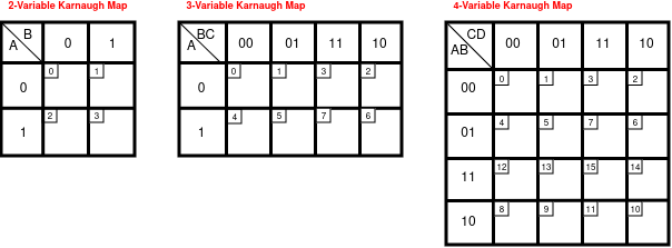
The order in which the truth table elements are mapped may look surprising:
the axes don’t work by counting up by 1 at each step.
Instead, we
choose an ordering that ensures only one variable
changes at a time as you move down a column or row.
So instead of having 10 next to 01, which switches both bits, we have 11 next to 01 instead, because only one bit switches.
This strategy is called a Gray code ordering.
After you fill out all the cells with the circuit’s output value, the next step is to find groupings of 1 cells. (These 1 cells correspond to the minterms.) Groupings must follow these rules:
- All 1s must be a part of a group.
- No 0s can be a part of a group.
- The grouping size must be a power of 2 (1, 2, 4, 8, etc.).
- Groups are always rectangular (no diagonals).
- Overlapping groups are allowed.
- Wrapping around the map is allowed.
- To find optimal groupings, you would also make the groups as large as possible and have as few as possible.
Here’s an example K-map for a 4-input truth table:
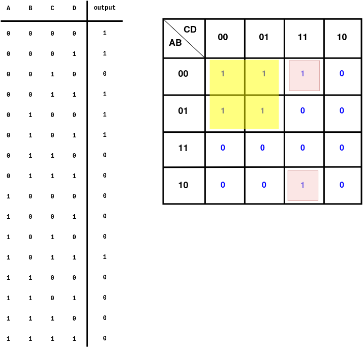
There are multiple valid groupings. We have shown a solution with two groupings, which is the smallest possible number for this truth table.
Each grouping represents an implicant (a Boolean expression that covers one or more minterms). To find the Boolean expression for an implicant, observe which variables change in a certain grouping and which variables remain constant. Include only the variables that remain constant in the expression.
In our example, here are the expressions for our groupings:
-
Yellow group:
Implicant in compact notation:0x0x
In standard notation: ¯A¯C -
Pink group:
Implicant in compact notation:x011
In standard notation: ¯BCD
Finally, to create the final Boolean expression, combine the expressions with an OR. The final expression here is:
¯A¯C+¯BCD
K-maps are amazing at quickly simplifying smaller boolean expressions and are great for humans to visualize. However, this approach does not scale well. Because K-maps are reliant on human pattern recognition and are done by hand, they are not often used for anything beyond four input variables.
Try Out Karnaugh Maps
Let’s try out the K-map technique! We’ll use the approach for the logic underlying a 7-segment display, like on a microwave:
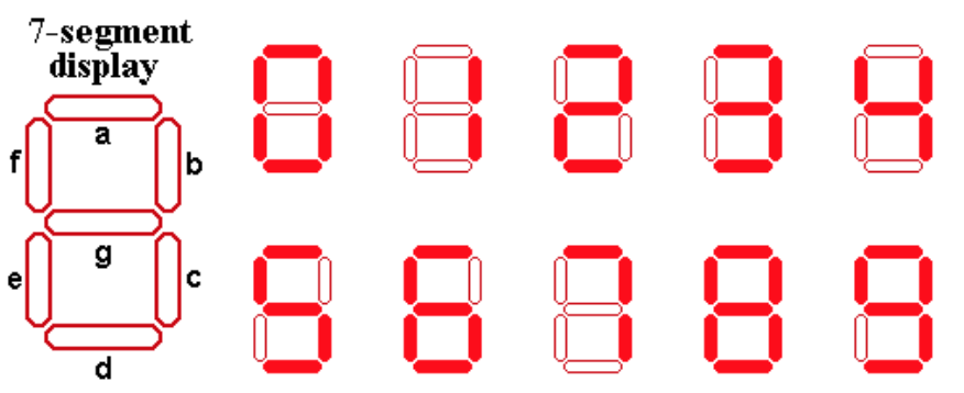
The idea in this lab exercise is to build the logic that takes in a 4-bit number representing a value from 0 to 9 and lights up the appropriate segments of the display.
For example, when the input is 0111, we want only segments a, b, and c to light up so the display looks like the number 7.
You can think of each segment having its own truth table that describes, for a given 4 input bits, whether it should turn on.
Step 1: Truth Table. Create a truth table for the top right section (segment b) of a 7-segment display. You only need to handle inputs in the range 0–9; other inputs are undefined. Write this truth table on paper. Here are the first few rows (with the output filled in only for the first one) to get you started:
| Input (decimal) | Bit 3 | Bit 2 | Bit 1 | Bit 0 | Segment b Result |
|---|---|---|---|---|---|
| 0 | 0 | 0 | 0 | 0 | 1 |
| 1 | 0 | 0 | 0 | 1 | |
| 2 | 0 | 0 | 1 | 0 |
We’ve augmented this truth table with an extra (leftmost) column where you can write the decimal value of the 4-bit number. The first row’s output is 1 because, to make the shape of the number 0, the top-right segment is turned on.
Step 2: Minimize Using a Karnaugh Map. Use the K-map technique to minimize the circuit for the “top right” segment. Remember, you will need to:
- Draw an empty 4-input K-map.
- Fill in the cells with the outputs from your truth table. For the cells where the output is undefined, because the input number is greater than 9, fill in 1s.
- Try to find the fewest, largest groupings of 1s in your K-map.
- Write the corresponding implicants.
- Join the implicants with “or” to write the final Boolean expression in standard notation.
Try to convince yourself that your new, simplified expression is a correct description of segment b’s behavior.
Checkoff #2: Show your Karnaugh map and your minimized Boolean expression to your TA.
Task 1: Finding All Prime Implicants
In this task, you will implement the first part of the Quine-McCluskey
algorithm where you must find all prime implicants for a given set of minterms.
Your implementation will go in quine_mccluskey.c.
You will implement these five functions:
checkDashesAlign: A helper function formergeMinterms.checkMintermDifference: A helper function formergeMinterms.mergeMinterms: A helper function forgetPrimeImplicants.addMinterm: A general helper function.getPrimeImplicants. The main function for this task.
Read quine_mccluskey.h for the specifications for all of these functions.
At a high level,
the idea is that we can merge two terms of the same length if both of these conditions are met:
- Their “don’t-cares” (
x) appear in the same positions. (There is no position where one term has anxand the other has a0or1.) - They differ in at most a single position.
The helper functions checkDashesAlign and checkMintermDifference check these conditions.
We have designed this assignment so it does not require dynamic memory allocation (malloc).
But it is not forbidden.
Handling the String Inputs
Here’s are some hints for how to use the arrays of strings that get passed to these functions. Remember that C strings are null-terminated arrays of characters, and some functions receive arrays of these arrays as arguments.
For example, one of the parameters to getPrimeImplicants is the minterms:
char minterms[MAX_TERMS][MAX_LENGTH].
You can think of this as an array of strings, or as a 2D array of characters.
There can be at most MAX_TERMS minterms, and each one can have at most MAX_LENGTH characters.
But in general, there will be fewer terms than the maximum, and each term will have fewer characters than the maximum.
Because strings in C are null-terminated, remember that the last character is always '\0' (the null byte).
In an empty string, this is also the first character!
Our code uses empty strings for the “unused” terms.
So to iterate over all the (non-empty) minterms, you can iterate until you find a string whose first character is null, like this:
for (int i = 0; minterms[i][0] != '\0'; i++) {
    /// ...
}
Then, if you want to iterate over all the characters in a given string, you can again iterate until you hit a null byte. For example, this prints out all the characters for all the minterms:
for (int i = 0; minterms[i][0] != '\0'; i++) {
    for (int j = 0; minterms[i][j] != '\0'; j++) {
        fputc(minterms[i][j], stdout);
    }
    fputc('\n', stdout);
}
Task 2: Selecting Prime Implicants
In this task, you will
select a reduced subset of prime implicants.
Your implementation will again go in
quine_mccluskey.c.
You will implement one function: findMinimizedPrimeImplicants.
As always, it is OK to implement your own helper functions if you want.
The idea with this step is that some prime implicants can be redundant, and it’s possible to select a subset that suffice to cover all the minterms. Here’s an example:
- Start with these minterms:
010,101,110,111 - Our approach in Task 1 would produce these prime implicants:
x10,1x1,11x - However, it suffices to keep only these selected prime implicants:
x10,1x1
This smaller set of selected prime implicants covers the full set of minterms.
Here is an algorithm to select a smaller set of prime implicants:
- Find all essential prime implicants. These are prime implicants that cover at least 1 minterm that is not covered by any other prime implicants. The specific algorithm to achieve this is described below.
- Check if the essential prime implicants covers every minterm. If so, we have found the minimal list of prime implicants.
- If the essential prime implicants do not cover every minterm, we must add some prime implicants to our finalized expression to cover every minterm. The specific algorithm to achieve this is described below.
Finding Essential Prime Implicants
To find all essential prime implicants, you will want to construct a 2D chart
comparing minterms and prime implicants. Set up this chart with the minterms on
the top and the prime implicants on the left. Fill in this chart, indicating
what minterms are covered for each prime implicant. For example, using the
previous example’s minterms 010, 101, 110, 111, and the prime implicants
x10, 1x1, 11x, we can create the following chart.
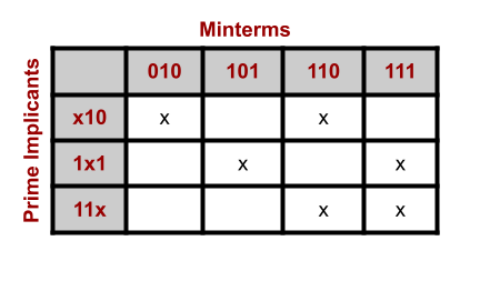
From here, we can easily identify essential prime implicants by looking for any
columns that contain only one X. In our example above, we see the minterms
010 and 101 fit this description, only being covered by the prime
implicants x10 and 1x1 respectively. Therefore, x10 and 1x1 are
essential prime implicants and must be included in the boolean expression.
In this specific case (although not in general), the essential prime implicants
also cover the remaining minterms of 110 and 111. Therefore, we can comfortably
drop the prime implicant 11x from our final set of prime implicants while
maintaining full coverage of our minterms.
We recommend that you declare a 2-dimensional array of bools to implement this chart.
You can declare it like this:
bool chart[MAX_TERMS][MAX_TERMS] = {false};
That initializes every entry in the 2D array to false.
Covering Remaining Minterms
If our list of essential prime implicants do not cover every minterm, we will use the following procedure to find remaining prime implicants:
- For every minterm:
- If it is not yet covered:
- Iterate over all inessential prime implicants to find one that covers the uncovered minterm, and add it to our set.
- When we do add a new prime implicant, mark all the minterms it covers as covered (so we don’t attempt to cover them again). (Remember that prime implicants might cover more than one minterm!)
- If it is not yet covered:
For example, suppose we have the minterms 1001, 1101, 1111, 0111, 0110
and the prime implicants 1x01, 11x1, x111, 011x. For the sake of brevity, you should find the eseential prime implicants to be 1x01 and 011x. However, these do not cover the minterm 1111.
- First, we try to cover
1111. By looking through all the inessential implicants (11x1andx111), we find that11x1suffices to cover this minterm.
So our final set of implicants is 1x01, 011x (the original essential prime implicant),
and 11x1.
Please also iterate over the minterms and prime implicants in the order the function receives them. This will make your solution match ours, which will make autograding go more smoothly.
Just for fun, if you want an extra challenge, you can try implementing Petrick’s method. Unlike our simpler strategy here, Petrick’s method finds minimized circuits. (Please do not submit this code if you try it!)
Task 3: Tests
Running and Testing
We have included a few example inputs in the tests/ directory.
Inputs are text files with one minterm per line, like this:
100
001
101
111
To run your implementation on one of these inputs, first compile it:
rv gcc -o quine_mccluskey quine_mccluskey.c
Then, run your program on an input file:
rv qemu quine_mccluskey tests/cout.txt
(Pick a filename and provide it as a command-line argument in place of tests/cout.txt.)
The program will write the selected minterms to output.txt.
Visualizing Your Circuits
Are you curious to see what the circuit schematics would look like for your simplified expressions? We have included a tool to draw these for you! This is completely optional.
The tool is implemented in Python, and it has some dependencies you need to install. A command like this might work:
python3 -m pip install -r requirements.txt
Then, if you already have some minimized implicants in a file output.txt, then you can run this to see a schematic:
python3 generate_circuit.py
Provided Tests
We’ve included some tests named mux.txt, cout.txt, input3.txt, input4.txt, and input5.txt. Use these to help debug your program as necessary.
Here are a descriptions of two of these tests:
-
The multiplexer (mux) selects one of two inputs based on a select input.
- Minterms:
010,101,110,111 - Prime Implicants:
x10,1x1,11x - Selected Prime Implicants:
x10,1x1
- Minterms:
-
The full adder has 3 inputs: A, B, and CarryIn. It has 2 outputs: Sum and CarryOut. Here is the logic for the CarryOut output:
- Minterms:
011,101,110,111 - Prime Implicants:
x11,1x1,11x - Selected Prime Implicants:
x11,1x1,11x
- Minterms:
Creating Your Own Tests
For the final part of this assignment, you will make five additional input tests that are different from the ones we supply. Make up some truth tables that compute interesting Boolean functions, and check that your implementation works correctly on them.
Turn in a file tests.txt that lists your five tests.
For each test, include in tests.txt:
- The list of minterms.
- A one-sentence description of what the circuit computes.
Your tests can do anything you like, as long as they do not match our tests. Be creative!
Submission
What to submit:
- A complete implementation in
quine_mccluskey.c. - 5 test expressions, in
tests.txt.
Rubric
- 80 points for
quine_mccluskey.c. - 20 points for the tests