

Breps are produced with the modeling routines, and are input to the mesh generator. They can also be exported to and imported from external packages if they are saved in the correct file format.
Abstractly, a brep is an acyclic directed graph. Every node in the graph stands for a face of the brep. The term face refers to a vertex, edge, facet, or higher dimensional bounding face of the brep. In addition, the interior of the brep is also considered a face. Each of these nodes has some information associated to it; for instance, vertices have their space coordinates associated with them. The arcs of the directed graph indicate boundary relationships. For example, an edge that is bounded by two vertices has arcs to those two vertices to indicate the bounding relation. A facet has arcs to the edges that act as its boundary. In general, a face of dimension k has boundary faces of dimension k-1. A face may also have "internal boundary faces" of dimension k-1 or any lower dimension; internal boundaries are discussed below.
A brep has two integers associated with it: its embedded dimension, which is the dimension of the space it lies in, and its intrinsic dimension, which is the dimension of the object itself. For instance, a square sitting in the z-coordinate plane of 3-space would have intrinsic dimension = 2 and embedded dimension = 3. The QMG functions follow the convention that the empty set has intrinsic dimension = -1.
Each face of the brep (node in the graph) has the following items associated with it:
color,
which is used by the graphics routines.
gm_poly and the
routine for reading
OFF format
require as input only a subset of the above information, and
they deduce the rest.
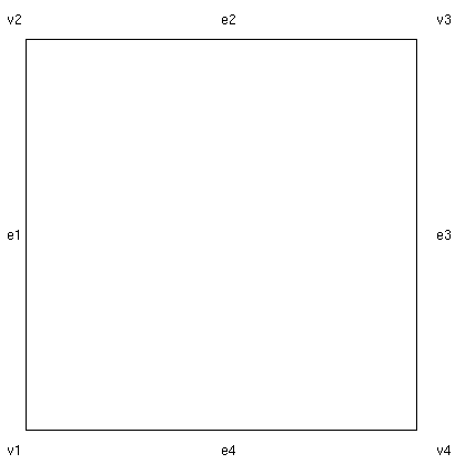
The brep for the square displayed above would have four faces of level 0, four faces of level 1, and one face of level 2. Suppose we refer to the vertex as v1,..,v4 in clockwise order, and the edges as e1,....,e4. Then the children of e1 are (v1,v2). The children of e2 are (v2,v3). The children of e3 are (v3,v4), and the children of e4 are (v1,v4). The square itself has (e1,e2,e3,e4) as children.
Internally, the faces of a brep are numbered consecutively 0, 1, 2,
etc. on each level. This internal numbering is used by the
many functions including
gm_addpropval
and
gmgetf.
In this documentation and in the code, we use the term
"facespec" to denote the specification of a face of a brep as
an ordered pair (k,i), where k is the dimension of the face
and i is this index in the consecutive numbering.
Facespecs are
used to label vertices simplicial complexes (see below).
Except for the fact that the ordering induces this numbering, the order of the faces in a level is not significant. Similarly, the order of children in the childlist is unimportant. In particular, it is not necessary to list the edges of facets in any kind of sequential order. The order of property-value pairs is unimportant.
As with a brep, a simplicial complex has two integers associated with it, the embedded dimension and the intrinsic dimension. A simplicial complex is specified by three arrays. The first array is the list of vertex coordinates. This array has a number of rows equal to the number of vertices, and a number of columns equal to the embedded dimension of the complex. The entries in this array are floating point numbers.
The second array is a list of simplices. The number of rows in this
array is the number of simplices and the number of columns is the
intrinsic dimension plus one. The entries of this array are
nonnegative integers that refer to the vertices (i.e., to row numbers
in the coordinate array). These vertex are numbered starting at 0 so you may
have to increment them by 1 if you retrieve them with
gmget(scomplex,'Simplices')
in Matlab, since Matlab numbering always starts with 1.
The third array is a list of facespecs. There is one facespec for each vertex of the simplicial complex. A vertex's facespec is its source specification: it indexes the lowest-dimensional brep face in the brep from which the mesh was generated. These labels are necessary for finite element analysis, because the boundary conditions are stored in the brep faces, and thus the finite element solver must know which face owns each vertex of the mesh.
Notice that this array specifies the brep face but does not actually specify which brep gave rise to the mesh generator. In the current version of QMG it is the user's responsibility to keep track of which brep gave rise to which simplicial complex. This is a known difficulty with the QMG data structures that may be addressed in future versions.
Qmg_Brep
and Qmg_SimpComplex,
which are documented in the source code
documentation. The C++ data structures are created while the
functions are running, but they are deleted as soon as the functions
finish so the user never accesses them directly.
The second representation is called the chunk representation, because in this representation the brep or simplicial complex occupies a contiguous chunk of memory. The chunk representation has been designed so that it can be easily unpacked into a C++ data structure and vice versa. The chunks are stored as Matlab arrays or as Tcl/Tk strings. (In the Tcl/Tk string version, the chunk is first expanded into two printing characters per byte. This is because Tcl/Tk cannot handle strings with embedded bytes equal to 0.) Most QMG functions that take breps or simplicial complexes as arguments expect the arguments in chunk format.
The actual entries of these arrays are meaningless to Matlab and Tcl/Tk,
and the user should not attempt to directly access or modify individual
entries of a chunk argument. (QMG routines do not verify the
correctness of a chunk argument before processing it.
Therefore, they may throw a
segment-violation/general protection fault
if an erroneous chunk argument is processed).
Chunk arguments may be saved in files using the Matlab
save command, but they should not be saved with
save -ascii command. If chunk arguments are saved
in a file, the file should not be shared between different architectures
because the encoding and decoding of the chunk arguments is
processor and compiler dependent.
The third representation of a brep or simplicial complex is as an Ascii string. QMG1.1 supports several different such formats, but there is one in particular that we refer to as "Ascii" format documented in this page. The other ones are for external interfaces.
The routine for conversion ascii-to-chunk is called
gm_in
and the inverse conversion is called gm_out.
See below for the details on the Ascii
representation.
Other formats for inputing and outputing breps and simplicial complexes include
gmoffread and
gmoffwrite)
gmchacowrite),
gmmpout), and
gmq10in).
There are many ways to create breps, access face information,
and modify breps; see information about
low-level brep constructors,
high-level brep constructors,
a low-level simplicial complex
constructor gm_simpcomplex
or
mesh generation functions for constructing
simplicial complex. See also information about
accessors.
Another method in the current system to construct a
brep from scratch is to write a string with an ascii-format brep and
then call gm_in
on the string. See the listing of
gmcone.m/gmcone.tcl for an example of this technique.
The advantage of this technique is that gm_in can deduce
information about affine hulls and points in the relative interior
if it is not specified in the string.
Internal boundaries usually serve one of two purposes in a scientific computation: they act as demarcations between separate regions of the domain (for instance, the domain may represent an object that is a composite of several materials) or they act as ``singular'' boundaries, for example, in modeling a region with a slit or crack.
Note that ``holes'' in a domain are not internal boundaries -- they are classified as ordinary boundaries.
Internal boundaries are useful because the mesh generator will respect them in its mesh (i.e. mesh elements will not cross through them). They can also be the site of boundary conditions for the finite element package.
Here is a simple example of an object with an internal boundary:
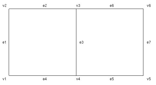
There are two kinds of internal boundaries supported by the QMG package: MTL internal boundaries and SL internal boundaries. The above figure could be of either kind.
MTL stands for ``multiple top-level.'' This means that the top level of the brep has multiple entries, i.e., the brep has more than one full-dimensional face. (``Top-level'' refers to the top level of the abstract acyclic graph representation described above.) The following graph indicates abstractly how the above double-square could be realized as an MTL domain.
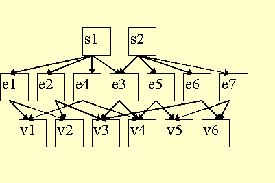
The point is that each of the two top level entries is a valid two-dimensional face (each is a square) but they happen to share a subface.
MTL internal boundaries are constructed with the
gmsplit routine.
An SL internal boundary corresponds to a ``slit.'' SL internal boundaries are stored separately from the childlist of the object.
If an SL internal boundary of a k-face happens to have dimension k-1, then it behaves in all contexts like a child in the childlist of a face that is repeated twice (and hence acts like a slit). In fact, SL internal boundaries of dimension k-1 can be stored in this fashion (as children that occur twice in the childlist).
Here is how the above double-square object could be represented as an object with an SL internal boundary by repeating entries in the child list.
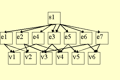
SL internal boundaries can be created with the
gmsubtract routine.
From the geometric point of view, SL internal boundaries are more general than MTL internal boundaries, i.e., any internal boundary that can be described as an MTL internal boundary can also be described as an SL internal boundary. SL internal boundaries are more general because they can be used for internal boundaries that cut only partway through the domain.
Even though SL boundaries are more general, MTL internal boundaries are preferable in the case that the internal boundaries represent demarcations between different zones of the domain. In the presence of MTL internal boundaries, the mesh generator will label interior nodes that it generates with the top-level face in which they lie (i.e., the label indicates which ``side'' of the MTL internal boundary the node lies on). See the description of source specifications of simplicial complexes above. The finite element program can take advantage of the labels during matrix assembly because it can use different functions to compute conductivity and source terms for the two sides of the MTL internal boundary.
In the case of an SL boundary, there is no concept of one ``side'' of the internal boundary versus the other since an SL boundary may cut only partway through the domain. Thus, all interior nodes have the same label. The conductivities can still vary as an SL internal boundary is crossed, but in this case the function that computes conductivities will have to use the position of the node in some kind of geometric computation of its own to figure out the conductivity for each mesh element.
The two types of internal boundaries, MTL and SL, can be freely mixed. In addition, an SL internal boundary does not actually have to be inside the face that contains it (although it has to be in the right affine hull). There is generally not much use for internal boundaries exterior to the face, and some routines will behave oddly for such an object, but it is a legal feature of QMG in order to allow the complement operation to take complements of objects with internal boundaries.
The mesh generator will produce a single ``layer'' of nodes
along either an SL or MTL internal boundary. In some applications
a double-layer of nodes is desirable. It is possible
to produce a double layer of nodes along an SL boundary
with
gmdoubleib.
gmcheckbrep checks
all these properties.
These definitions allow unbounded breps. For instance, a ray in QMG can be represented as a 1-dimensional object with a single child (the starting point of the ray). An object of dimension 1 or higher with no child faces is an infinite affine hull.
The remaining correctness properties of breps are:
For mesh generation, some additional correctness properties are needed.
The correctness properties of a simplicial complex are as follows. The geometric set associated with a simplex is defined to be the convex hull of its vertices.
If a simplicial complex is specified in conjunction with a brep (i.e., it is a putative triangulation of the brep), it must satisfy the following additional correctness conditions. Suppose it is a triangulation of the k-dimensional faces of the brep.
gmchecktri tests all of these
correctness properties in linear time (that routine assumes
correctness of the brep) with its An important property of a simplex is its aspect ratio. The aspect ratio of a simplex can be defined in several ways which are all equivalent up to constant multiples. In the QMG package, aspect ratio is defined as the ratio of the length of the longest edge of the simplex divided by its shortest altitude.
Small aspect ratios are desirable because large aspect ratios cause a loss of accuracy in the finite element approximation, and can also lead to condition number problems for the assembled stiffness matrix.
If the simplicial complex is not full-dimensional, the rules are as follows. Suppose the simplex lies an a brep face F whose affine hull is given by Ax=b. Note that A is not uniquely determined, so any A is acceptable, but we require that every simplex on a given face must choose the same A matrix.
In the case that the brep face is one lower dimension than d, A has one row. If this face is a bounding (child) face of exactly one d-dimensional brep face of the brep, then we additionally stipulate that the row of A is an outward-pointing normal to the face.
In any case, once A is selected for the brep face, the orientation rule is that the matrix formed by appending to the end of A the rows v1-v0,...,vd-v0 (which now will be a square matrix) must have positive determinant.
The delimiters for crossproducts are <...>. The delimiters for a list are (...). That is, the sequence of items enclosed in <...> are of possibly different types, and the type of each entry is known in advance from its position in the sequence. The items enclosed in (...) are all of the same type, and the number of items enclosed in (...) is not necessarily determined in advance syntactically.
The idea of representing a brep as recursively nested crossproducts was suggested by S. Allen.
The rules for an Ascii representation may be defined by the following production rules.
brep or
simpcomplex.
nil .
nil
terminates the recursion; the depth of the nesting before nil
is encountered must agree with the intrinsic_dim specification above.
For common cases, the user never has
to specify either the affine_rhs or affine_coef property-value pairs
because gm_in will deduce them automatically by looking
at the vertices of the face. The exception is when the face is infinite,
in which case there may not be enough vertices to determine the affine
hull. Similarly, the user generally does not have to specify
the point property either---as long as the face is finite,
QMG can automatically deduce the point.
The exception to this latter rule is 0-dimensional faces, which must
be accompanied either by a point property or a
affine_coef and affine_rhs property, otherwise
QMG cannot figure out the position of the vertex.
gm_poly.
In three dimensions the OFF format is easier to work with.
But these other formats do not support internal boundaries
or infinite breps,
and OFF does not support facets with holes (facets
bounded by multiple "loops"). If you do not need any of these
features, then you can use one of these simplified formats.
If you need the full power of the Ascii format, then you will need to prepare a list of vertices, edges, and facets of your object. For the vertices you need coordinates; for the edges you need to know endpoints (as specified by the names or indexes of the vertices), and for facets you need to know the bounding edges.
Here is an example of the square at the beginning of this document
written in Ascii format.
The line breaks are not significant. As mentioned
above, the names used in this brep,
v1, v2, etc. are fairly arbitrary strings
and are not stored in the chunk or C++ form
of the brep. They are only used by
< brep
 < 2 2
  < (
   < v1 (< point (0.0 0.0) >) () () >
   < v2 (< point (1.0 0.0) >) () () >
   < v3 (< point (1.0 1.0) >) () () >
   < v4 (< point (0.0 1.0) >) () () >
   )
   < (
    < e1 () (v1 v2) () >
    < e2 () (v2 v3) () >
    < e3 () (v3 v4) () >
    < e4 () (v1 v4) () >
    )
    < (
     < s1 () (e1 e2 e3 e4) () >
    ) nil >
   >
  >
 >
>
gm_in as symbolic tags
to link the faces to their children correctly.
The following is the Ascii format
of a simplicial complex that is a triangulation of the
above brep using two triangles.
<simpcomplex
 < 2 2
 (
  1.0 0.0
  0.0 0.0
  0.0 1.0
  1.0 1.0
 )
 ( 0:1 0:0 0:3 0:2)
 ( 0 3 1
   1 3 2
 )
 >
>
This documentation is written by Stephen A. Vavasis and is copyright (c) 1996 by Cornell University. Permission to reproduce this documentation is granted provided this notice remains attached. There is no warranty of any kind on this software or its documentation. See the accompanying file 'Copyright' for a full statement of the copyright.
Stephen A. Vavasis, Computer Science Department, Cornell University, Ithaca, NY 14853, vavasis@cs.cornell.edu