CS631 Final Project
 
3D Morphing
 
Suwat Chitphakdibodin
 
Glen C Chang
 
Thibet Rungrotkitiyot


   1. Abstract
 
The previous two-dimensional shape transformation technique, feature-based morphing, has been widely used in computer animation industry.  The effect and variation of the techniques have gained popularity and been used for producing special effects in commercial and entertainment.  The algorithm works by specifying a function that maps pixels from a source image into pixels on the destination image.  The intermediate frames are created by interpolating a
point between the two objects.  When the intermediate frames are views in sequence, it produces an animation of image transformation.

This project presents another way in creating animation of object transformation.  The provided technique transforms polygon-based three-dimensional objects instead of the conventional two-dimensional image.  This project presents one of the possible techniques used in transforming polyhedral 3D objects.  This technique utilizes topological and geometric information obtained from the original 3D models in establishing intermediate object’s vertices, edges, and faces.  This three-dimensional shape transformation technique is useful in producing the more complex type of special effect animations than the one obtained from two-dimensional morphing algorithm.  They could be used in virtual reality application such as 3D-computer games and entertainment world.
 
Furthermore, this project explores a few variations in obtaining different morphing scheme such as objects' center selection and non-linear non-symmetric polygon interpolation.  All results can be found later in this paper and in application section.
 
Keywords :  Computer Animation, Polyhedral Object Model Construction, OpenGL Computer-Aided Geometric Design, Shape Topological Transformation and Interpolation.


   2. Introduction
 
In order to transform a three-dimensional object into another, two intermediate models must be constructed, such that it contains both topological and geometric information from both source and destination object.  The two intermediate models will have the same amount of vertexes, edges, and faces.  Each vertex, edge, and face of the source model uniquely corresponds with vertex, edge, and face of the destination model.  This part of constructing two merge topological models is called establishing correspondence problem.  After the correspondences have been created, the actual transformation can be created by interpolating each corresponding pair of vertex, edge, and face.  The part of the problem is called interpolation problem.  Figure 1 below shows the two intermediate models created from topological information of both original three-dimensional objects. It also shows the interpolation phase after the two intermediate models are created.


Figure 1 : Shape Topological Transformation
(Download Animation File)
 
This paper presents an algorithm that can automatically establish the correspondences by Weiler in [1].  It can easily transform two three-dimensional polygon-based objects by transforming the two generated intermediate models that have each of their vertexes, edges, and faces, one-to-one associated to each other.  There are limits to this algorithm which will be discussed later in this paper along with some of the possible solutions used in breaking the limitation and handling some other types of specific cases.


   3. Fundamental Concept
 
There are some essential terms discussed throughout the paper.  It is useful to describe and define a few of these key concept.  The term object represents an entity whose surface is a set interconnected polygon that forms a 3D surface geometry.  The shape of an object is the set of points in space that made up the object’s surface.  Model is a complete description of the shape of an object.  Topology refers to a network of vertices, edges, and faces of any objects. When vertices of a topology is specified in coordinate, it forms geometry.  Two objects are topologically equivalent, or homeomorphic when a continuous one-to-one mapping function between points on each of the two object’s surface exist.  That mapping function is called homeomorphism.  Last, an object is Euler-valid if its topology satisfies Euler fomular:
 
V - E + F = 2 - 2G
 
Where V, E and F are, respectively, the number of vertices, edges and faces of the topological network, and G  is the number of passages through the object (i.e. its genus).
 
An object is considered a star-shaped object if at least one polyhedron’s interior point, p, that sees all the other points on the polyhedron’s surface, exists.  The interior point can see all the point on the objects’ surface if every constructed semi-infinitely long ray originating at the specified interior point, p, intersects other point on the surface exactly one time.  Moreover, an object can be considered a convex-hull object if every interior point within the object sees all the other point on the object’s surface. The figure 2 below shows some example of these specific types of three-dimensional objects.
 
1
2
3
4
Convex Hull Object : Every interior points see every point on its surface. 
 
Star Shape Object: There is at least one interior point that sees every point on its surface. Non Star-shaped object: There is no interior point that can see every point on its surface.  Object with hole is considered a non-start shaped object since such a point is not exist. 
 
Figure 2 : Object Classes
 
It is quite simple to implement an algorithm identifying which object is convex hull, star-shaped, or non-star-shaped.  For an object to be convex hull, each angle formed by two neighborhood faces must be less than or equal to 180 degree from perceptively to object’s interior.  For an object to be considered a star-shaped, the angle can be greater than 180 degree but the sum of all the excess of 180 degree angle along the object’s surface edges must not exceed 180 degree. Any other objects that do not satisfy the above rules are non-star-shaped object.


   4. Shape Transformation Algorithm
 
As discussed earlier, the algorithm consists of two main parts, the correspondence establishment problem and the interpolation problem.  Both parts are closely related.  The interpolation phase relies on the output of the correspondence establishment. part of the problem.  The result must be a one-to-one correspondence of each of topological elements of the two.  The presented algorithm in this paper is only capable of transforming star-shaped objects.  At the end of the paper, some possible solutions used in transforming non-star-shaped objects are also presented. The technique relies on the way to break up these non-star-shaped objects into a set of smaller pieces of star-shaped objects and individually transform each of them accordingly. The algorithm is working well with a curtain kind of non-star-shaped object transformation, such as the transformation of star-shaped objects with interior hole.


   5. Establishing Correspondence
 
The two intermediate models are constructed by adjusting the topology of original models by projecting topology of the original models on each other. Essentially, it clips surface from the first original model and put it on the second original model and from the second original model on the first model.


Figure 3 :  Correspondence Establishment
(Download Animation File)
 
 
Figure 4 :  Center Offset Selection
(Download Animation File)
 
Both constructed intermediate models contain identical topology information from both original models; however, the geometry is not yet similar. In the second phase, the interpolation algorithm smoothly adjust each correspondence pair of vertex, edge, and face in both constructed model until the geometry is entirely transformed from one to another. The figure 3 above shows the two original models, source object transformation and destination object transformation, and two constructed intermediate models.  The figure 3 above shows the placement of object's center effects the geometry mapping.
 
 
Projecting State

Throughout the paper, the original polyhedral model will be referred as M1 and M2.  V1 and V2 are the list of vertexes in the corresponding models M1 and M2.  E1, E2, F1, and F2 are the list of edges and faces in the corresponding models.  The algorithm 
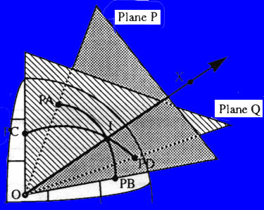
works by projecting each model on the surface of a unit sphere.  The projected model of M1 on the unit sphere is called PM1, and the projected model of M2 is called PM2. The projection algorithm is very simple. It can be done by constructing a ray from the center point, the point that is used as the center of the transformation, to each vertex. This center point must be an interior point that sees all the other point on the object’s surface in that case the transformation object is not a convex hull object. The vertex is moved in either positive or negative direction along this ray until the unit distance from the center point is obtained. Please noted that after all the vertex are moved to a unit
distance away from the center point, object’s edge remain connecting the same two vertexes.  However, it new projected edges are no longer a straight line but an arc connecting the same two 
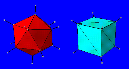
adjusted vertexes that lies along the sphere surface.  Figure 5 below shows an example of how topological elements, including vertexes, edges, and faces, of a star-shaped polyhedral three-dimensional object is projected on the surface of the unit sphere.


Figure 5 : Sphere Projection
  
 
Weiler’s Clipping Algorithm State (Merging and Adjusting Topology)

After the projection, both PM1 and PM2 have sphere geometry with a different set of faces that form a complete cover of the unit sphere surface.  Then each face on either one of the projected models, PM1 and PM2, is clipped and pasted on the other model forming a common topology.  The sphere is chosen as the common projection geometry because of its ease to implement; however, other types of geometry can be also used.  For example, two-dimensional flat plane can also be used for model’s topological elements to be projected on.  This paper discusses only the projecting on unit sphere technique.
 
      
    Read in the Topology and Geometry of Each Model 
      
    For Each Egde of Each Model 
      Project the Edge onto the Unit Sphere 
       
    (Modified Weiller Clipping Algorithm) 
    For Each Projection Edge (Arc) of Model 1 
      For Each Projection Edge (Arc) of Model 2 
        Calculate Arc/Arc Intersection Point 
        If Arcs Intersect 
          Subdivide Arcs at Intersection Point 
          Adjust Edge Topology 
           
    For each Projected Vertex, PV 
      If PV is not an Original Vertex of Model 1 
        Map PV to Model 1's Surface
      If PV is not an Original Vertex of Model 2 
        Map PV to Model 2's Surface 


Figure 6 : Psuedocode for the Correspondence Algorithm
 
Weiler’s polygon clipping algorithm is used for clipping the arc bound surface from one of the object to another.  This algorithm is used in this project. Essentially, Weiler’s clipping algorithm is just an algorithm that adds new edges and vertexes from one of the projected model on the other and adjusts its topology according to the new edges and vertexes added. If projected arcs intersect, an extra vertex located at the intersection point is added to the topology. The edges involve that intersection point will also be spirited into to new projected arcs. These intersection vertexes are also located along on the sphere’s surface with unit distance from the center point. The algorithm is repeated until all the edges and vertexes from PM2 are mapped on the surface of PM1 or vice versa. There is a simple way to calculate the location of the intersection points. We know that the intersection point is also located on the surface of the unit sphere.  We define a plane P and Q according to the figure 7 below.


Figure 7 : Weiler's Correspondence Algorithm
 
PA and PB are the projected points of the vertex A and B of the first original model, M1. PC and PD are the projected points of the vertex C and D of the second original model, M2. PC and PD and the edge PC-PD of the PM2 are clipped on the PM1 to create the common model. The intersection point is simply a point along the ray OX that has a unit distance from the center point, O.

Continue to Next Page
 
Created and  maintained by Suwat Chitphakdibodin.
This page was last modified on Friday May 1, 1998.
Contact the author suwatch@cs.cornell.edu
 
Back to Top