Assignment 5: Interactive image selection, part I
Graphical User Interfaces (GUIs) enable richer human–computer interaction by responding to more kinds of input, such as mouse movements, and presenting users with more dynamic output, such as animated graphics. The capabilities and configurations of a program become more discoverable when they can be controlled via familiar graphical “widgets” like buttons, menus, and sliders. Moreover, object-oriented toolkits, like Swing, make GUIs easy to build (some IDEs, including IntelliJ, even let you drag-and-drop widgets to form a GUI).
But programming an interactive application requires some different techniques from what you’ve used so far, namely inversion of control. Instead of prescribing the order of operations yourself, your program must respond to whatever the user decides to do, typically by executing event handlers that you have defined and configured to “listen” for certain user actions or data changes.
Of course, before any of this can happen, the interface itself needs to be defined. Designing an attractive and usable interface is an artform, and GUI toolkits provide a wealth of reusable and customizable components to help you realize your vision, but assembling them in code by hand can admittedly be rather tedious.
In this project, you will complete an application that allows users to copy subjects out of images, saving their selection to a new file. You will write code to assemble the interface, keep track of the selection process, draw the selection boundary, and handle a variety of user interactions. In the process you’ll work with Swing components both from inside (inheritance) and from the outside.

While this assignment will give you practice programming GUIs, it is also intended to give you practice learning new skills from reference materials. You will be using widgets, layout managers, and event handlers that have not previously been shown in lecture or discussion, and this is intentional. The release code includes numerous links to API documentation and official tutorial pages that directly relate to the new classes you’ll need to use, and reading and understanding this material on your own is a big part of the assignment.
Learning objectives
- Arrange standard widgets like buttons and file menus into a graphical user interface using Java’s Swing framework.
- Leverage standard dialogs to help users select files and inform them of concerns.
- Separate the concerns of an interactive application into Model, View, and Controller roles.
- Define the look of a custom component by overriding how it is painted.
- Respond to button activations, mouse movement, and mouse clicks.
- React to changes in model state using the Observer pattern.
- Interpret state transition diagrams and sequence diagrams to follow modal behavior and control flow in an interactive application.
Recommended timeline
Don’t try to do this assignment at the last minute. You will need to look at a significant amount of API documentation, and you don’t want to be trying to ingest that while in a hurry. Note that consultants will expect that you have already read the relevant Swing tutorials when you ask for assistance diagnosing issues.
There are about 23 TODOs to complete. Here is one way to spread out the work:
- Day 1: Read the “functional requirements” and “getting started” sections of this handout. Familiarize yourself with the structure and contents of the release code. Complete the tasks in “step 1.”
- Day 2: Read the handout sections on Model–View–Controller, Observer, and the selection model and familiarize yourself with the model’s state transitions. Read the provided source code for
SelectionModelfor awareness of which methods are available to clients and to subclasses and which serve as helpers to others. Complete the tasks in “step 2.” - Day 3: Read the source code for
SelectionComponentand compare it with the sequence diagrams in the handout to get a sense for how various objects interact in response to events. Complete the tasks in “step 3.” - Day 4: Complete the tasks in “step 4” (these are the most difficult parts of the assignment).
- Day 5: Continue implementing, testing, and debugging the features from “step 4.” If you finish early, complete some of the embellishment tasks or attempt the challenge extension. Respond to the questions in the reflection document. Have fun using the program to cut out stickers!
Collaboration Policy
On this assignment you may work together with one partner. Having a partner is not needed to complete the assignment: it is definitely do-able by one person. Nonetheless, working with another person is useful because it gives you a chance to bounce ideas off each other and to get their help with fixing faults in your shared code. If you do intend to work with a partner, you must review the syllabus policies pertaining to partners under “programming assignments” and “academic integrity.”
Partnerships must be declared by forming a group on CMSX before starting work. The deadline to form a CMS partnership is Friday, November 8, at 11:59 PM. After that, CMSX will not allow you to form new partnerships on your own. You may still email your section TA (CCing your partner) to form a group late, but a 5 point penalty will be applied. This is to make sure you are working with your partner on the entire assignment, as required by the syllabus, rather than joining forces part way through. New groups may not be formed on or after the due date.
As before, you may talk with others besides your partner to discuss Java syntax, debugging tips, or navigating the IntelliJ IDE, but you should refrain from discussing algorithms that might be used to solve the problems, and you must never show your in-progress or completed code to another student who is not your partner. Consulting hours are the best way to get individualized assistance at the source code level if you get stuck diagnosing an issue on your own.
Frequently asked questions
If needed, there will be a pinned post on Ed where we will collect any clarifications for this assignment. Please review it before asking a new question in case your concern has already been addressed. You should also review the FAQ before submitting to see whether there are any new ideas that might help you improve your solution.
Assignment overview
The end goal (“functional requirements”)
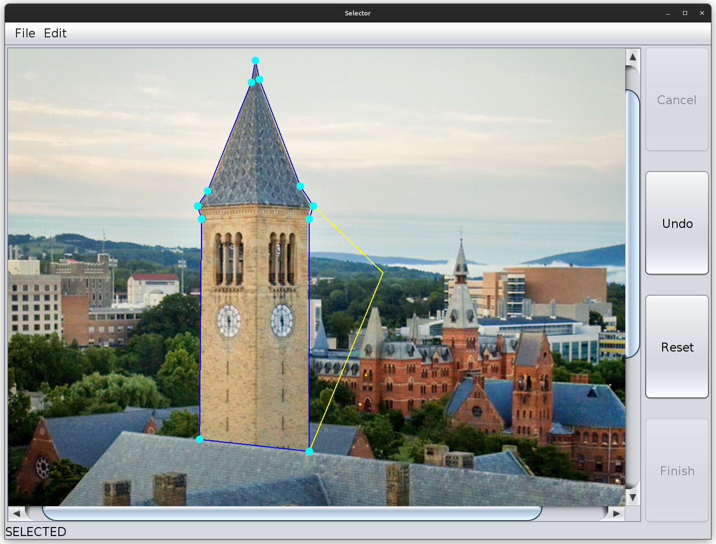
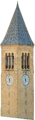
The Selector application should allow users to open an image file, draw a selection around a region of the image, then save their selection as a new file (analogous to a “sticker” in smartphone messaging). To draw the selection, the user will click a sequence of points. By default, the points will be connected with straight lines, forming a polygon (we’ll call this “point-to-point” selection). However, other selection modes are available, and in a future assignment, you will implement a more sophisticated tracing tool that automatically follows edges in the image. To accommodate these different selection modes, the core functions required to make and manipulate a selection have been collected into an abstract base class.
 →
→
After the selection (shown in blue above) has been drawn, the user will have the opportunity to move any of the polygon’s vertices (shown as cyan disks above) by clicking and dragging on them. Additionally, the user can “undo” to erase the edges that have been added to their selection one-by-one (for simplicity, however, they won’t be able to undo a move). When choosing a new point or moving an old point, the application will draw guide lines from neighboring points to the current mouse location (shown in yellow above).
It is helpful to make a list of the user actions (verbs) that the application needs to support. These include:
- Open an image from a file
- Add points to a selection by clicking
- Finish the selection by connecting back to the starting point
- Undo the most recently added point
- Reset the selection (undoing all of the points)
- Save the current selection to an image file
You will also see a disabled “cancel” button in the design; this will be used in the next assignment to interrupt a computational task that is taking too long.
As you browse the application’s source code, you will see several tasks marked “TODO (embellishment)”. These do not alter the core functionality, and they require reading more sections of the Java tutorial, but the make the application nicer for users. They are not worth many points and should be postponed until all of the functional requirements have been met. Once you have a functional application, come back to these embellishments and tackle a few to customize the app to your liking. Keep track of which embellishments you complete in your reflections.
Getting started
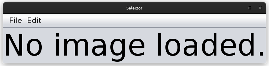
Open the release project in your IDE and try running SelectorApp; you should see a window with a file menu at the top.
Take note of the classes that make up this application. Here is a brief tour of them:
- SelectorApp.java
- Represents the overall application. Responsible for setting up the GUI window and dictating how the application should respond to various user events. Portions of this class have already been implemented, but you are tasked with completing it.
- ImagePanel.java
- Represents the portion of the user interface that displays the image and facilitates interaction with it. When no image is loaded, it displays the text “No image loaded.” (do not modify)
- SelectionComponent.java
- Represents a transparent user interface component that gets drawn on top of the image in an
ImagePanel. Responsible for reacting to mouse inputs on top of the image and for drawing the current state of the selection. - SelectionModel.java
- An abstract base class for tracking the state of a “selection” of a region of an image as it is built up segment-by-segment. Subclasses are responsible for deciding how to extend the selection when a point is added or moved (e.g., by connecting points with straight lines, or by tracing subjects in the image).
This file also defines theSelectionStateenumeration, which is used to describe which “mode of operation” the app is in at any given time.
- PointToPointSelectionModel.java
- A concrete subclass of
SelectionModelthat connects points with straight lines. You will need to implement logic for adding and moving selection points that achieves this straight-line behavior. - PolyLine.java
- Represents an immutable sequence of 2D points with integer coordinates, with line segments implied between each pair of adjacent points. Each “segment” of the application’s selection path is represented by such a poly-line. In this assignment, most poly-lines will be simple line segments containing only two endpoints, but in the next assignment, segments will have more complicated shapes. (do not modify)
- tests/…/PointToPointSelectionModelTest.java
- A test suite for
PointToPointSelectionModel. Since the model does not do any painting or listen for any user inputs, we can test it with good-old-fashioned JUnit tests. - lib/SplineSelectionModel.jar
- A pre-compiled implementation of a selection model based on Bézier splines, which connect every other point by smoothly bending towards the points in between. By constructing an instance of
SplineSelectionModel, you can interactively test yourSelectionComponentto make sure you didn’t make too many assumptions that are only true forPointToPointSelectionModel. (There is nothing to see in this file; its presence in the “lib” dir is enough to allow you to construct instances ofSplineSelectionModels.)
The code you need to write is marked with TODO comments. Each item is numbered in the order we recommend completing it in.
This is not the order in which they appear in the files.
This handout gives tips on how to test your changes along the way, but if something doesn’t work, you will need to debug your code.
Debugging event-driven code can be tricky; a general tip is to add println() statements to each method so you can distinguish between a buggy method implementation and a bug that prevents the method from being called in the first place (just remember to remove all such print statements before submitting your code).
There are too many widget types and properties to cover them all in lecture, so you will need to learn how to use the ones you need yourself.
Get comfortable with the API pages for classes like JComponent, and browse some of the Swing Tutorial.
When a TODO references tutorial pages, read them thoroughly so you know how to use the component it describes.
Most importantly, play around—since a GUI is interactive, you can see the effects of small changes right before your eyes.
Step 1: Expanding the basic layout
You’ll start your work in SelectorApp.
Browse its fields, then read its constructor and its makeMenuBar() helper method.
To complete the main application window, you’ll need to add a status bar, scroll bars, and eventually buttons.
Complete TODOs 1A & 1B, then run the application again to check that your changes had the desired effect (you may need to resize your window for the scrollbars to appear).
Now it’s time to display an image.
From reading makeMenuBar(), you’ll note that activating the “Open” item under the “File” menu will result in openImage() being called.
Jump to that function (you can click on its name while holding down Ctrl [Windows, Linux] or ⌘ Cmd [Mac] in IntelliJ), then complete TODO 1C.
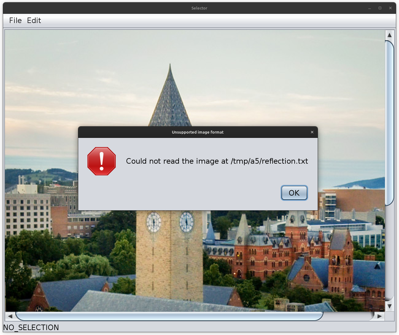
This task requires using three new classes from Java’s standard library: JFileChooser, JOptionPane, and ImageIO.
The code you need to write isn’t much more complicated than an if statement and a try-catch block, but first you need to teach yourself how to use the Application Programming Interfaces (APIs) that these classes provide.
Read the linked tutorial pages thoroughly, follow along with their examples, then return to this assignment to finish the tasks.
When you’re done, you should be able to activate File | Open, select the image bundled with the assignment, and see it displayed in the application window.
You should also test opening a non-image file (by changing “Files of Type” to “All Files”) to check that your error dialog works.
Interlude: the Model–View–Controller and Observer patterns
Modular, maintainable software is designed by following the principle of separation of concerns. In a graphical application, some of these concerns include drawing the user interface, responding to user input, and maintaining application “state”. These concerns are related, but also separate.
For example, if you rename a file in IntelliJ, you expect the new name to be shown in the project browser. However, you would also expect the new name to be shown there if you renamed the file using your operating system instead, even though you didn’t type the new name into IntelliJ. And you expect file names to be shown not just in the project browser, but also in your editor tabs. A single piece of application state (a file’s name) may need to be drawn in multiple parts of the user interface, and it may change either as the result of user input or through other mechanisms. Therefore, it would not make sense to handle everything related to file names in a single class.
A common way to organize the responsibilities of an interactive graphical application is to divide them into Model, View, and Controller roles (MVC):
- Model
- The application state. May be updated by Controller code. Notifies observers when state changes.
- View
- Displays the application state to users and receives user input. Responsible for re-drawing the graphical interface as necessary when the Model changes.
- Controller
- Responds to events, including user-input events received from the View, by updating the Model and/or changing the View (such as popping up a dialog).
With this decomposition, it is possible for multiple View components to show data from the same model in different ways, both updating when the Model changes and neither responsible for knowing how those changes get made.
Note that this decomposition does not have to be strict, and there are many variations.
In Swing, it is common for Views and Controllers to be tightly coupled in the same class, while the Model is a separate class.
For example, SelectorApp both assembles UI widgets in its window (View) and listens for their events, dispatching them to the appropriate application-specific functions (Controller).
Likewise, SelectionComponent both draws the current selection boundaries (View) and interprets mouse events that occur over the image (Controller).
But both share a SelectionModel (Model), which can even be used independently of any graphical display at all (e.g., in a unit test).
These roles typically communicate with each other via the Observer pattern.
Objects that produce events maintain a list of listeners.
When events occur, each of the listeners is notified by calling a method on it.
A Controller may observe View components by registering listeners for user input events.
And both Views and Controllers may observe Models by registering listeners for property change events so that they can react when the model’s state has changed.
SelectionModel has a field named propSupport that helps it keep track of these listeners and to “fire off” events that they will be notified of.
Warning: Earlier in the course we talked about “observer methods;” they are not related to the “observer pattern” being discussed here, but both employ the word “observers.” Use context to disambiguate the term. For example, “Observers (the role in the observer pattern) may call observers (accessor methods) in order to get updated information about the state of an observed model object."
Step 2: The selection model
The SelectionModel class models how a “selection path” drawn on top of an image can grow, shrink, or move over time.
It is an abstraction that provides the following behaviors related to our functional requirements:
addPoint: Append a segment to the path, connecting its last point to the given point.undo: Remove the most recently added segment from the path, or remove the starting point if there are no segments yet.finishSelection: Close the path by appending a segment connecting its last point to the starting point.movePoint: Change the location of a point that joins two segments in a finished selection.save: Extract the image pixels contained in the selected region and write a new image with those pixels (the rest of the rectangular region around those pixels will be transparent).reset: Remove all segments, as well as the starting point, from the path.
Not all of these behaviors make sense all of the time, and some might behave differently in different circumstances.
For example, it wouldn’t make sense to try to save a selection before a selection has been finalized, so we should disable any “save” buttons in that situation.
It would be helpful to represent the current “status” of the selection model with an object.
We’ll use a dedicated supertype to represent that status, SelectionState, which declares methods for querying which operations are currently valid (e.g., canUndo(), isFinished()).
Different selection models have different statuses, so each subclass of SelectionModel will define its own unique subtype of SelectionState.
These subclasses are Java enumerations (enums), which restrict them to a handful of pre-defined values.
Review the JavaDoc comments for the values of PointToPointState to understand their meaning.
For convenience, the current selection state is always shown in the status bar you added in TODO 1A.
It stays in sync because SelectorApp listens for changes to the “state” property of the model and invokes its reflectSelectionState() method in response, which updates the label’s text.
Once we’ve identified these states, we need to define how a SelectionModel can transition between them, typically in response to an operation.
These rules are easiest to express visually using a state transition diagram, as shown below for PointToPointState.
Each operation that can be performed in a state is depicted as a labeled arrow, showing which state the model will be in after the operation is performed.
For example, if a client invokes addPoint on a model that is in the SELECTING state, it will remain in the SELECTING state.

PointToPointSelectionModel's state. Each circle represents one of the values of PointToPointState, and each arrow shows which state the model transitions to when the labeled operation is performed.If an operation is invoked in a state where that operation’s behavior is not defined (for example, saving when the state is not SELECTED), than an IllegalStateException should be thrown with a message indicating the current operation and state.
Implementing and testing SelectionModel
Study the class invariants for SelectionModel, and read the code of the methods that have been implemented for you to understand how they are achieving their specified effects.
Pay particular attention to the segments field, which is a LinkedList of segments of the selection path, as well as the controlPoints field, which is a LinkedList of points used to define the segments (note: for point-to-point selections, the control points are the endpoints of the segments, but this may not be true for other selection modes).
A Java LinkedList can be used as a List, a Queue, or a Stack (since it implements both the List and the Deque interfaces); you will be responsible for deciding which of these ADTs’ operations best meets your needs.
Obviously, adding points to the selection is pretty important behavior, so direct your attention to the addPoint() method.
Its behavior depends on the current state: it might start a new selection, append to an existing selection, or thrown an exception if the selection is already finished.
The release code implements everything needed to start a new selection, and the testStart() case over in PointToPointSelectionModelTest walks through such a scenario.
But one of its assertions depends on the lastPoint() accessor method, which has not yet been implemented.
Complete TODO 2A and confirm that the test now passes.
This should get you familiar with thinking about SelectionModel’s states and fields, and you may find lastPoint() to be a useful helper when completing your next tasks.
The scenario in testStart() only covers the case where a starting point has been chosen but the end of the first segment has not.
There are a couple of other test cases that start from a similar setup: testLiveWireStarting() and testUndoStarting().
The latter should pass out-of-the-box, but the former needs your help.
The purpose of liveWire() is to provide a preview of the segment that would be added if its argument were added as the next control point (this will allow the View to draw the preview as the mouse moves without modifying the selection until it is clicked).
However, while the endpoints of that segment are fixed by liveWire()’s specification, it’s allowed to take some twists and turns in between.
It is the job of subclasses of SelectionModel to specify that in between behavior.
PointToPointSelectionModel adopts the simplest behavior: a straight line.
Complete TODO 2B to override liveWire() in PointToPointSelectionModel; check your work with testLiveWireStarting().
In order to test non-empty selections, we need a way to add segments to the selection path.
As with live wires, the details are left to subclasses, which must override appendToSelection().
Complete TODO 2C in PointToPointSelectionModel, testing with testAppend() (which will also cover lastPoint() again).
Now that you can set up non-empty selection paths, you should check the behavior of other functions in that context.
Complete TODO 2D in PointToPointSelectionModelTest to test liveWire() again.
As you write your first test case on your own, pay attention to how the PclTester helper class is used to check behavior related to the Observer pattern (the class definition is at the bottom of the file).
This is handy for asserting that listeners have been notified of important property changes in accordance with function specifications.
Finally, what users can add, they should be able to undo.
Reading the implementation of undo(), you will see that it handles states that are “processing” as a special case (not used on this assignment), then delegates its work to the undoPoint() helper method (tip: Ctrl- or ⌘ Cmd-click to jump to this helper).
Complete TODO 2E to remove the most recently added segment and control point (you can assume that at least one segment exists, since the empty case is handled for you above).
testUndoSelected() covers undoing a finished selection, while TODO 2F asks you to test undoing while a selection is still in progress.
All the tests related to adding and undoing points should be passing now (we’ll come back to the others later). Those green checkmarks give us confidence to move forward with providing a graphical way for users to interact with this model.
Step 3: A UI for selections (view and controller)
Open SelectionComponent and read its code.
As a subclass of JComponent, instances of this class can be added to Swing GUI windows (and in fact, ImagePanel does precisely that).
We also see that it implements MouseListener and MouseMotionListener, suggesting that it will respond to mouse interactions.
Finally, the fact that it implements PropertyChangeListener suggests that it will be observing a Model in order to know when to redraw itself.
The class doesn’t maintain a lot of state itself (though it does maintain some to track ephemeral user interactions); rather, it contains an instance of SelectionModel, whose state it is responsible for visualizing and updating.
Your job will be to implement those event listeners to fulfill the component’s Controller duties, as well as to implement its paintComponent() method to visualize the selection represented by its model.
The flow of control for event-driven applications can be very difficult to trace, especially when the Observer pattern is used. To help you keep track of it, here are a pair of sequence diagrams illustrating what happens for two different mouse events. The participants in the interaction are arranged into columns, and time flows from top to bottom. Each solid arrow represents a method call—they point from the object that made the call to the object the method was invoked on; dashed arrows represent a returned value. The duration of a method (the time when its call frame is on the call stack) is shown by a tall rectangle.


These diagrams can help us keep track of responsibilities.
For example, user interactions that modify the selection model, such as clicking to add a point, do not need to request a repaint themselves, since that will be handled by the propertyChange() method that gets called in response to any model changes.
However, interactions that only affect temporary “interaction state”, such as moving the mouse to get a preview of the next segment, do need to request a repaint themselves.
The diagrams also show that the View only reads properties of the Model during painting.
Start with TODO 3A, which will allow you to interact with the model using mouse clicks.
To see what you are doing, implement TODO 3B to draw the outline of the current selection.
Note that this component’s paintComponent() method relies on four helper functions, which you will implement one-by-one.
You will need a good understanding of the coordinate system used when painting: the origin is in the upper-left corner, and y increases downward, as if it were counting rows of pixels in an image.
You will also need to familiarize yourself with the API of the Graphics class—at least one of its methods looks like a good match for our PolyLine class…
After implementing paintSelectionPerimeter(), run the app, open an image, and click in a few places to test your code (lines should appear after your second click).
A right-click should undo the most recently added segment.
If you have the ability to middle-click, that should close the selection by connecting back to the start (don’t worry if you don’t have a middle mouse button; you’ll be adding a “finish” button to the UI later in the assignment).
It would be even more interactive to have a preview of the segment that would be drawn as we move the mouse around; we call this preview a “live wire”.
You have already written code to return the appropriate segment, and the release code already implements mouseMoved() to save the last-observed mouse position in a field.
With that in mind, complete TODO 3C to draw the live wire to that saved mouse location.
Test your work by re-running the app.
To make the app a useful tool, we need to allow users to save their selections as new images.
Since not everyone has a middle mouse button, we need to add another way for users to finish their selections.
Return to SelectorApp and implement TODOs 3D & 3E to add a panel of buttons to the side of the image display.
This task involves both View work (creating and laying out the buttons) and Controller work (registering action listeners with each of the buttons).
Test that these buttons achieve their desired effects.
When testing your buttons, you may have encountered an exception printed to the console if you tried to activate one in a state where that behavior wasn’t valid. To provide a friendlier user experience, we should only enable a button when its behavior is valid. Fortunately, it is easy to disable and re-enable these widgets in response to events, including observed property changes.
SelectorApp already responds to changes to its model’s state by calling reflectSelectionState() (see propertyChange()).
Complete TODO 3F to enable and disable the application’s buttons and menu items as described.
Test your changes by running the application—hopefully you can’t trigger an IllegalStateException anymore, even if you try!
Multiple selection models
If your application doesn’t seem to be working right, you might have trouble determining whether the bug is in the Model (PointToPointSelectionModel) or in the View or Controller (SelectionComponent).
To help you debug, we have provided an alternative implementation of SelectionModel in compiled form: SplineSelectionModel.
Complete TODO 3G to add a “combo box” above your buttons from which a user can select between a “Point-to-point” model and a “Spline” model.
Test your application with the “Spline” model to confirm that your View generalizes to different kinds of selections.
When using the Spline model, a new segment will be added after every second control point, and the selection can only be finished when an even number of points have been added.
For example, if the selection is finished with 6 distinct points, then the segments will pass through points 0, 2, 4, and back through 0, and in between then will gently bend towards points 1, 3, and 5 without passing through them.
Finally, users need to be able to save the results of their work.
Read the implementation of saveSelection() in SelectionModel to check that you understand the steps required to do this.
In order to activate this function, complete TODO 3H back in SelectorApp.
Test your work by saving some selections and admiring them with your operating system’s image viewer.
Congratulations—you’ve assembled a functional GUI program! It even supports live previews and an “undo” feature to help users make careful selections with confidence. But what if a user doesn’t notice a mistake until they’ve finished their selection? Rather than undoing the whole thing, what if they could adjust individual points?
Step 4: Manipulating selections
Once a selection has been finished, the user should have the ability to move its control points by clicking and dragging them.
You’ll need to make changes across Models, Views, and Controllers to accomplish this.
On the View front, we first need to be able to see these control points.
Complete TODO 4A by implementing paintControlPoints() in SelectionComponent, then visually confirm that your points look consistent with the selection perimeter.
On the Model side, when a point is moved, the two segments it was joining need to be updated to go through the new point.
The path of these segments depends on which subclass of SelectionModel is active; the point-to-point model will again use straight lines.
Complete TODO 4B in PointToPointSelectionModel to update these segments.
Test it with the provided testMovePointMiddle() case, but be sure to write more tests of your own (TODO 4C).
If you have trouble with the specification or implementation of the movePoint() method, test cases are often a great way to think through the details of an example without first worrying about how the work gets done.
There’s one more Model task to take care of before moving on to the Controller for this interaction.
We need a way to know which control point a user clicked on.
Complete TODO 4D by implementing closestPoint() in SelectionModel.
A pair of test cases are provided, but you will need to write more (TODO 4E).
Now for the user interaction in SelectionComponent.
When clicking and dragging over a component, Swing generates three kinds of events: the mouse button being pressed (mousePressed()), the mouse moving while a button is pressed (mouseDragged()), and the mouse button finally being released (mouseReleased()).
For our interaction, we want to choose the control point when the mouse button is pressed, draw guide lines to the mouse pointer while the mouse is dragged, and ask the model to perform the move when the mouse button is released.
Complete TODO 4F in mousePressed() to call your closestPoint() function when a drag is initiated over a completed selection.
Since mouseReleased() has already been implemented for you, you should be able to test that you can move control points by clicking, dragging, and releasing (you won’t see visual feedback during the drag yet, but the point should move when you release).
To get visual feedback during the drag, implement paintMoveGuides() (TODO 4G).
Test that you now get visual feedback while dragging.
Congratulations!
That’s all the required functionality for this assignment.
Assuming that your application is behaving as you expect, you should be in a good place to enhance it during the next assignment, where you’ll implement a new, smarter subclass of SelectionModel.
Step 5: UI embellishments (2 points)
Once you have the above functional requirements working, if you have time, you can try to improve the user experience of the application.
Complete as many of the suggested embellishments as you can (search for TODO (embellishment)), which include improving colors, adding keyboard shortcuts, and handling corner cases when opening and saving files.
Document which embellishments you attempted in your reflection document.
You are also welcome to embellish your application in other ways (though no extra credit is awarded for doing so). Just be sure that:
- Your submission satisfies the functional requirements and adheres to given specs.
- Your GUI at least has the controls shown in the “wireframe” mockup at the top of this handout.
- Your tweaks do not require any changes to files other than those you are submitting.
Feel free to share embellishment ideas (and stickers) on Ed. Have fun!
Challenge extension (3 points)
As usual, this challenge extension will give you practice designing (and testing) your own classes and refining high-level requirements into specifications that you can implement. It requires a lot of work relative to the number of points it is worth, so you should only attempt it if you finish early and are comfortable that the rest of your submission is working correctly. TAs and Consultants may not be able to provide much assistance with challenge extensions.
Design and implement a class named selector.CircleSelectionModel (in “CircleSelectionModel.java”) that selects a circular region of an image.
The first control point should be treated as the center of the circle, and the second control point is a point on the edge of the circle.
The “live wire” should preview a circle passing through the current mouse location.
The PolyLines used to approximate the circle should be accurate to within a couple of pixels.
Because of how these control points are interpreted, it does not make sense to “finish” a circle selection by connecting back to the start.
Instead, the selection becomes complete after the second point is chosen.
Additionally, the “guide lines” drawn when moving points will not be particularly meaningful (this is fine).
When constructing a CircleSelectionModel from an existing model, it is fine to ignore any points or segments from the previous selection.
Add your circle selection model to the combo box and test it interactively. (You are also encouraged to write a unit test suite, but there’s no need to submit it.) Good luck!
II. Submission
In “reflection.txt”, estimate the amount of time you spent on this assignment, and answer the verification and reflection questions. Then submit the following files:
- SelectorApp.java
- SelectionModel.java
- PointToPointSelectionModel.java
- SelectionComponent.java
- PointToPointSelectionModelTest.java
- reflection.txt
- CircleSelectionModel.java (if attempting challenge extension)